Cargo Trike Construction Details - Page 2
Page 1 - Rear frame and pivot
Page 2 - Front frame
Page 3 - Completing frame details
Page 4 - Paint, Cargo Box, Lights, and Road Test
Page 5 - Getting the last bits done
Page 6 - Observations, and photos of working and playing.
Conclusion - when it's all said and done...
Update: revised front wheel and brake.
The front frame
Photos 24 through 48.
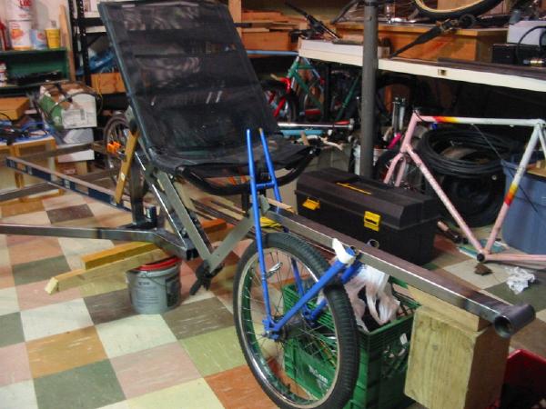
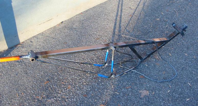
With the rear frame together, and the pivot are assembled, the next step of course was to get the front end sorted out. Some of the head-scratching was mitigated by certain constants; we knew that the main tube would run straight over the front wheel from the pivot to bottom bracket. And from there the seat height was more or less pre-determined. We did have to decide how much space there would be between the top of the front tire and the frame, and while I wanted to keep the seat height as low as possible, I did want to leave room for fender clearance in this area. The main variable was where in to position the seat in the horizontal plane. That is, how far ahead of the pivot, and how close to the wheel.
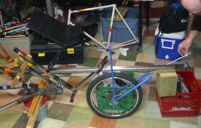
As you can see from the accompanying photos I had to do a more or less complete mock-up of how things would fit together. And here is where I made my first (and rather careless) mistake. Via email Dan Kavanaugh had told us the desired amount of negative trail, which I recalled at 5-6 inches. But that was back in the Spring of 2003, and here we were six months later finally putting it all together. Did I go back and check that email to make sure of that number? For some reason, no. And so that led us down the wrong path for a while, which included completing the front frame and adding the drivetrain. More on how we resolved that later on...
One thing I wanted to be quite sure of with this machine was that there would be no flex in the bottom bracket area! My Linear recumbent is a monotube design, and the flex in the BB is apparent under load. And so I did not want this same "feature" on my trike, and I decided that the front stays (that run up from the dropouts) had to meet with the BB. Dan's design has these stays coming up just ahead of the front wheel, and that allows him to use a sliding boom for different leg lengths. But knew that I would be the main driver, and the BB would be fixed and any adjustment would be in the seat area.
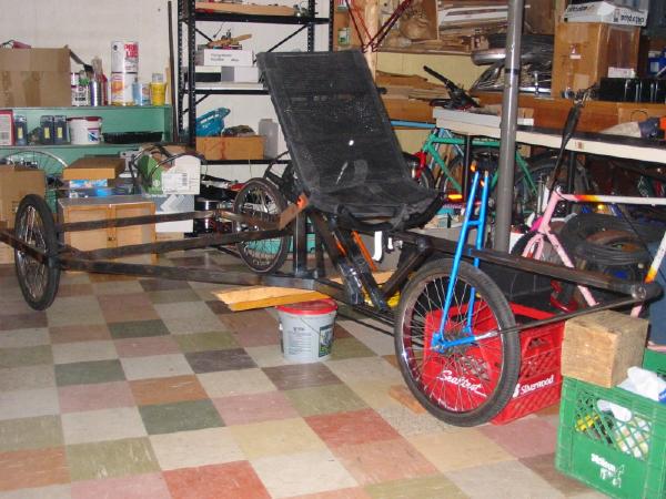
From the start we had hoped to have the trike accomodate riders of different sizes, so I could lend it out to friends. But with the limitation of the fixed BB, we knew that not everyone would be able get fit. And even a sliding seat design began to look like a lot more effort, so Juergen had the fine idea to weld in small tubes that the seat's front mounting bolt could fit into. Oh, and speaking of the seat, one area where we saved a lot of time and hassle as using an existingrecumbent seat. My brother had an old one from a Vision R-40, and it fit the bill quite nicely. If a seat *did* have to be constructed, the best plans I've seen are by .
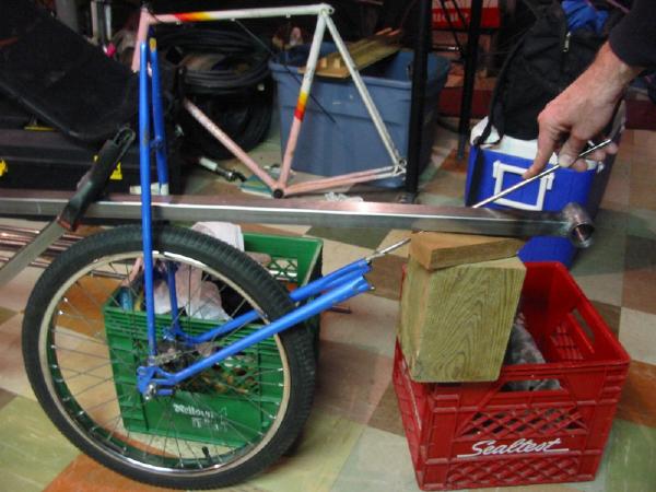
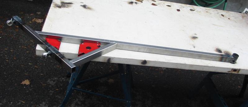
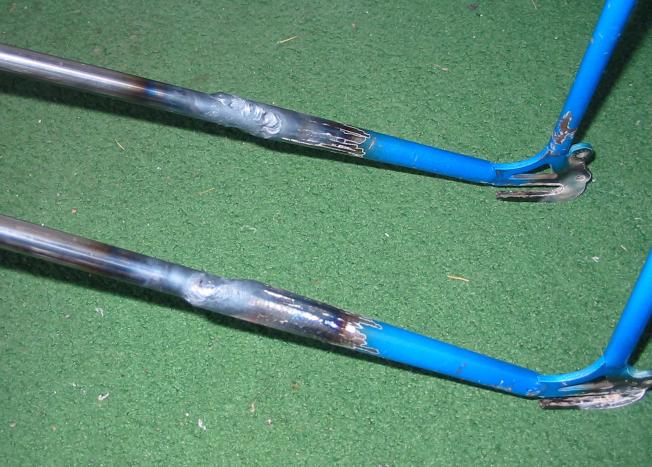
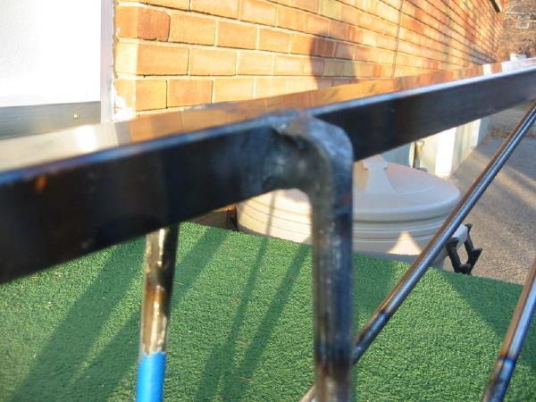
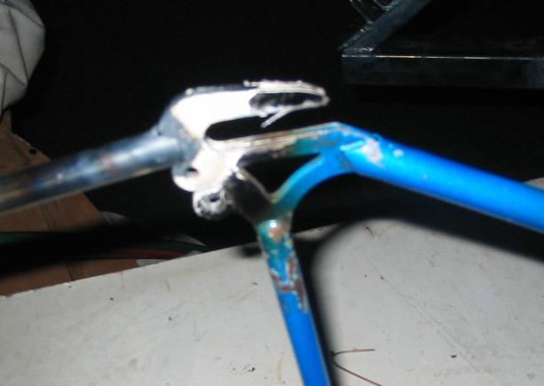
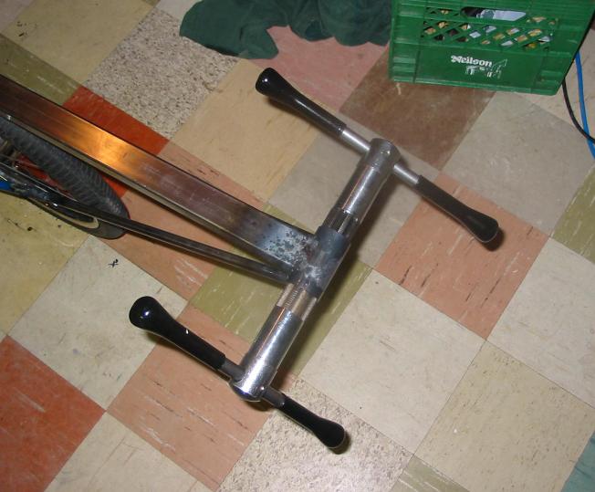
How to build around the front wheel made for an interesting debate. We ended up using the rear triangle of an old road bike, cut down with its axle spacing narrowed via cold-setting (that's a mechanic's term for bending. [grin]) The big challenge was welding this in place, because we had to line it up on three different planes - the wheel had to point straight ahead, but not too far up or down, and certainly not off to one side! Getting it perfect would have meant constructing a jig to hold the triangle in place with the main tube, but since we didn't want to spend the necessary time on that we just winged it!
(Speaking of the front wheel, I decided to use an internally-geared hub, as I had on hand an older Sachs 7-speed hub, and since it had a coaster (backpedal) brake it would simplify the trike's braking issue. I could use a lever on each handlebar to control each rear brake, instead of using one to control a front brake while the other would use a splitter to control the rear ones. Building this hub into a very sturdy double-wall BMX rim gave me my third wheel-building project, and it except for intially msessing up the spoke lengths it came out very well.)
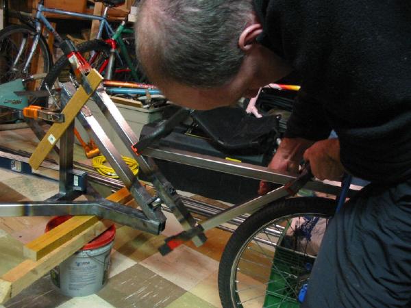
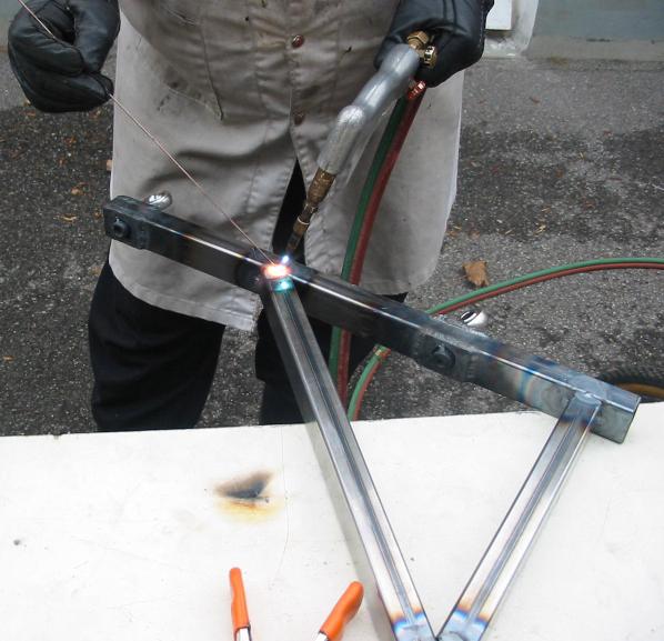
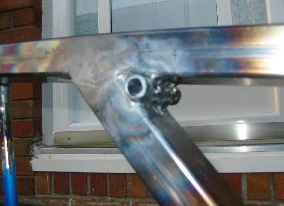
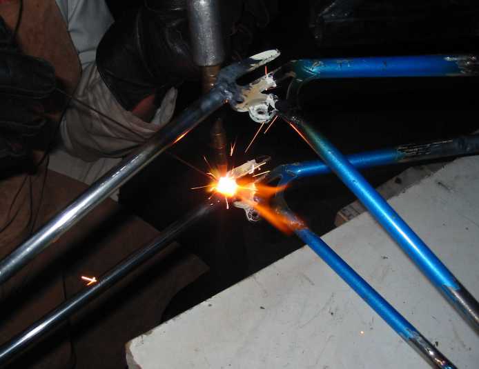
So with me holding things just about where we thought they should be, Juergen fired up the torch and we hoped for the best. And we came out pretty lucky! A little bit of cold-setting here and there, and it was straight. Since the top of the triangle was wider than the tube, we used small spacers made out of 1/2" tube (same as the other stays) to bridge the gap (narrowing the triangle would have made it too tight for a typical 20" tire). Once the triangle was in place and solid, we cut off the part sticking above the main tube, and hammered the remaining stubs down on top of the spacers (Juergen had fun with this, heating the stubs red-hot with the torch while hammering them down. It felt like we were forging something in a very medieval way!).
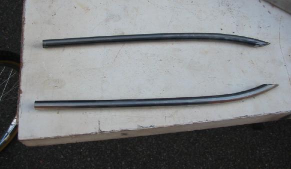
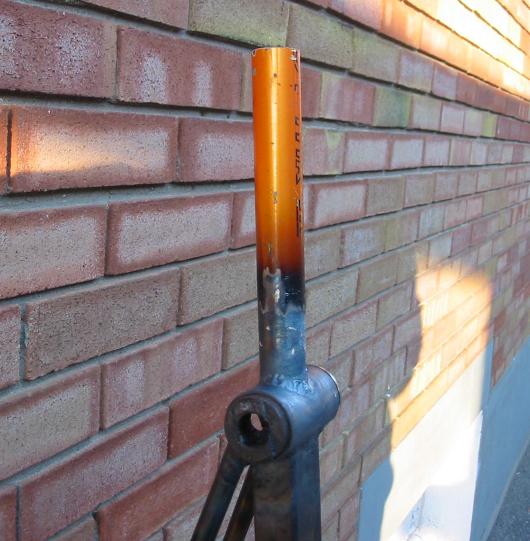
With the triangle in place, the stays were cut and added in, with the rear ones being filed at an angle so they could come up on either side of the pivot tube. The front stays were welded to the back end of the BB, and with the heat from this, as well as from welding the BB itself to the main tube, the threads in the shell got rather distorted, so I had to use a tap to chase them back into line again. The other end of the front stays were sleeved into the forward-facing tubes of the triangle and welded in.
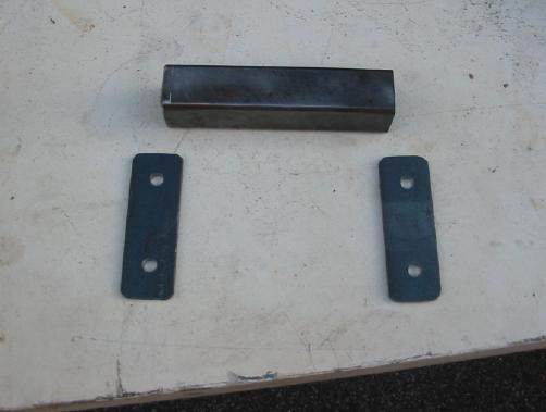
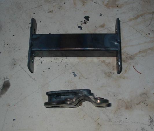
With cold weather approaching our desire to get this project finished made us decide to just build it to suit me, and version #2 could be made more adjustable. So only one front seat mount tube was welded in, just behind the join of the main tube and its connecting tube to the pivot. The upper seat mount was created out of 1" square tube and some drilled flat stock, as shown in the photos. It was welded to the top of the pivot tube, and a rear wheel quick-release was used to connect the seat to this mount.
|