Cargo Trike Construction Details - Page 1
Page 1 - Rear frame and pivot
Page 2 - Front frame
Page 3 - Completing frame details
Page 4 - Paint, Cargo Box, Lights, and Road Test
Page 5 - Getting the last bits done
Page 6 - Observations, and photos of working and playing.
Page 7 - Update: revised front wheel and brake.
Conclusion - when it's all said and done...
The rear frame and pivot
Photos 1 through 23.
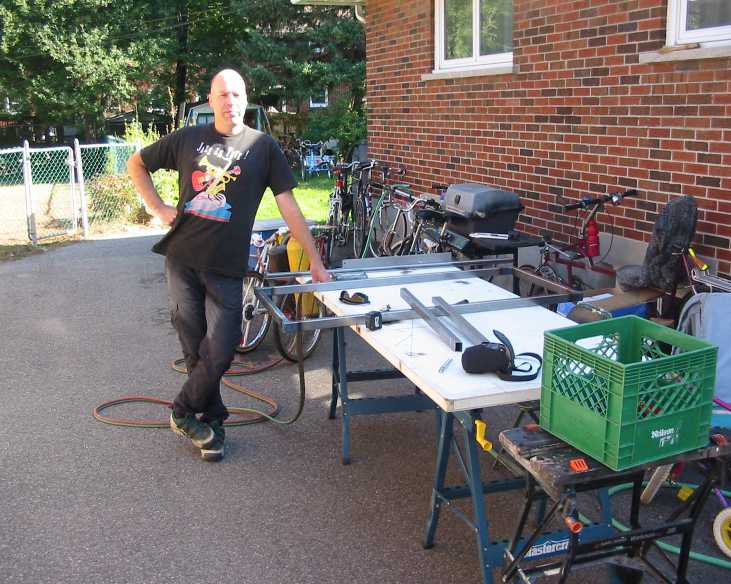
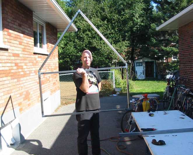
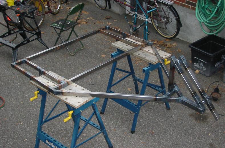
Once I had determined the dimensions of the cargo box, the rear frame had to of course be designed and built to accomodate this. The first batch of photos to the right show things getting started (notice the nice leafy trees, as we begain this project in early September of 2003. Snow will show up in later photos, indicating how long the build process took due to working with each other's schedules.)
We used 1" x 1.5" .065" mild steel for this, and it was supplied by the local , with Kevin and Adry providing helpful advice, especially on availability of different metals and tube sizes. (I guess I could have mail-ordered what they couldn't supply, but that takes time and money, and I also like to shop locally whenever possible.)
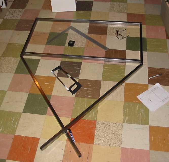
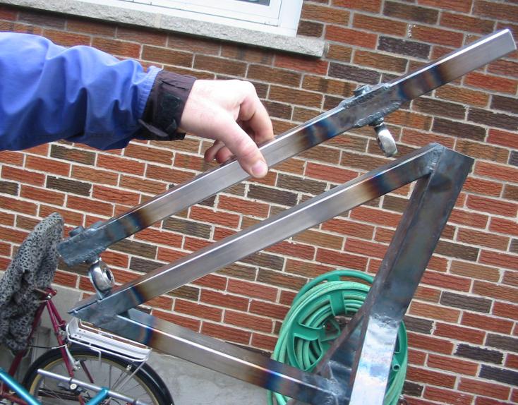
One thing we were not sure about was where exactly the end points of the triangle should meet. Everything depended on the 45 degree angle of the mid-ship pivot point, and we weren't entirely sure by looking at the photos of Dan's design how high the sloping tube would go. So we opted to fit things on the short side, rationalizing that it would be easier add more tube to the end of the triangle than to cut and shorten said triangle! Which is indeed what we ended up doing...
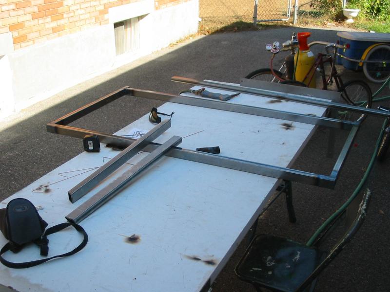
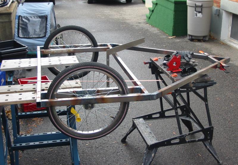
The first deviation from Dan's design was to include a cross-tube ahead of the wheelwells. Juergen and I thought this would added some strength in a critical area, and it allowed us to enclose the wheelwells squarely, instead of using the beginning angle of the horizontal triangle as Dan did (just trying to make our lives easier whilst prototyping!). While this extra tube will add weight (and in the end it could have been of thinner gauge and / or thinner size), the extra support under the cargo box means things could be loaded or even dropped in with greater impunity.
I should point out that pretty well all the measuring, cutting, filing and shaping of tubes and assorted bits was done in Juergen's basement workshop, and the camera was usually not at hand. But we seemed to always have that camera for outdoor use to show off Juergen's welding skills. That's what you get when the welder owns the camera! (wink)
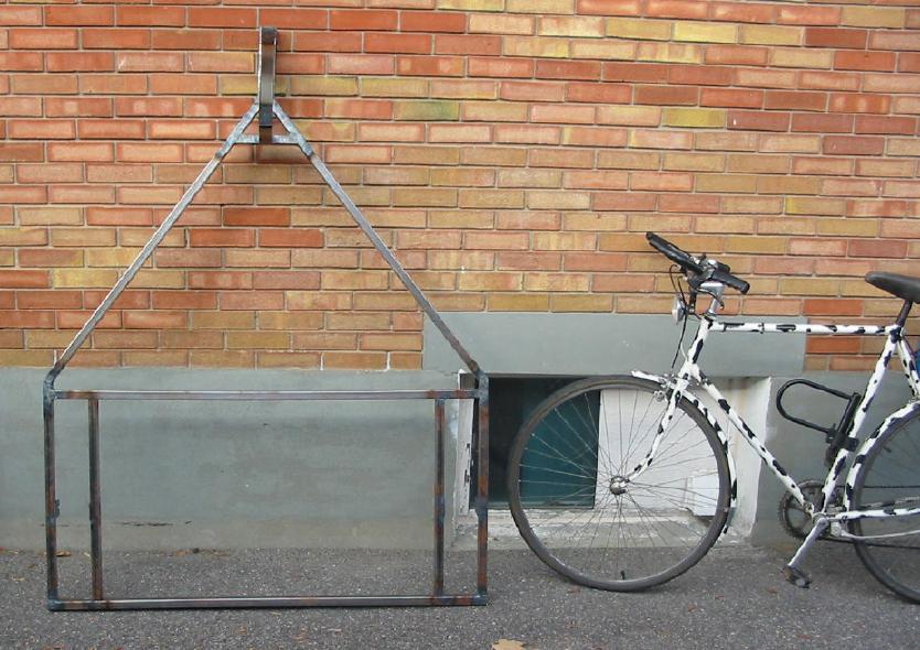
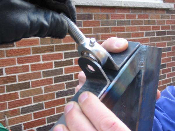
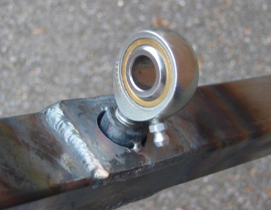
Once the main part of the rear frame came together we had to concentrate on the vertical triangular section that would define the 45 degree pivot point. We decided to use two 1/2" tie-rod ends, purchased from here in Ottawa. They were about $20 each with zirk (grease) fittings.
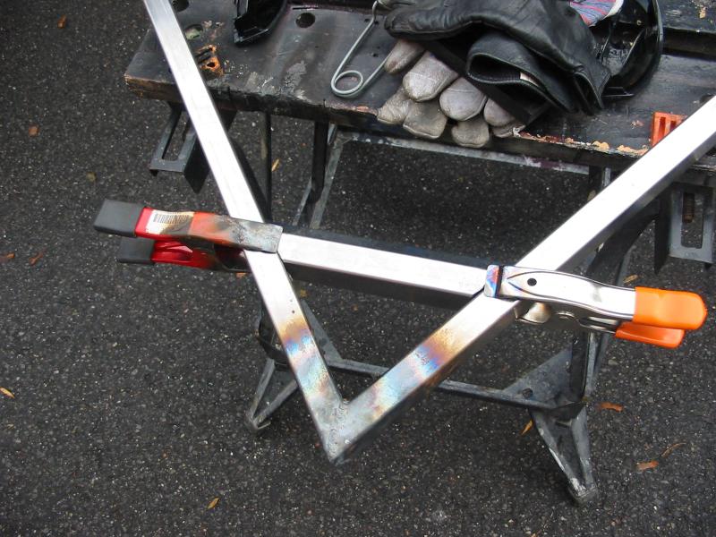
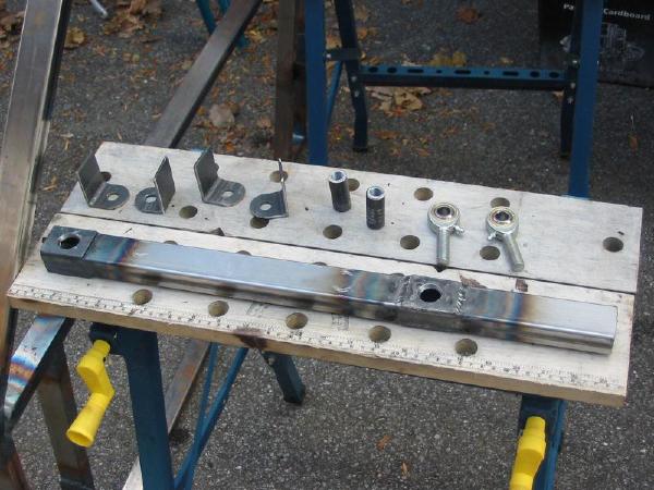
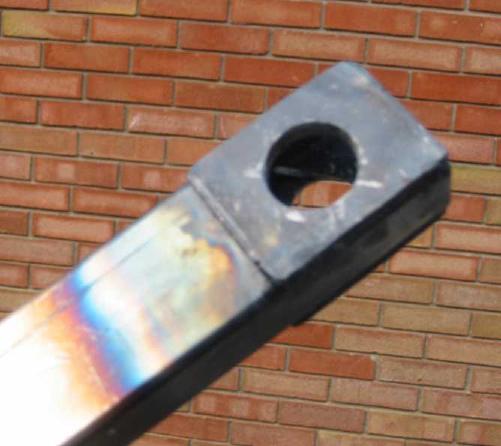
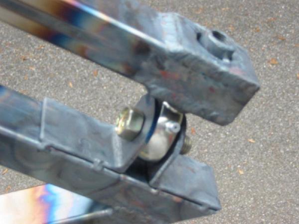
Dan's design used two pairs of these rod-ends, but Juergen got clever and suggested we use rod-ends on one tube, with corresponding L-brackets and large bolts receiving them on the other tube. Since the .065" tube wall would tear apart under the strain of the rod-ends, they of course couldn't just be threaded in without reinforcement. So we drilled extra-large holes, then cut two pieces of 3/4" thick-walled tube to fit in these holes and stick out slightly past the main tube's surface (to give the weld something to hold onto). We then figured out the size and pitch of the tie-rod's threads, and tapped these two small tubes (with lots of patience and cutting oil) to receive them. Let me tell you that we were very happy when the taps worked and it all came out straight!
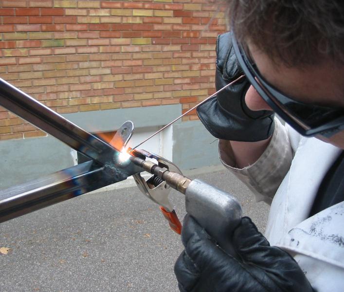
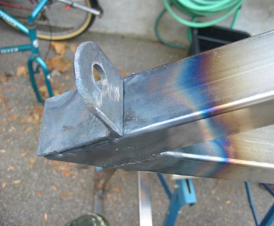
As we went along, Juergen would just lightly tack the pieces together. This would allow us to easily heat and break the tack if we found things to be out of alignment, and sometimes we could even just hammer things a little straighter and the tack would hold it. Only once we were happy with things would Juergen then take the time to get a good bead around each joint area.
We of course had to make sure that the tie-rods stood out from the tube as closely as possible to 90 degrees so that they would fit properly into the brackets. Most of you will have by now figured out that we weren't exactly working off a big set of blueprints! The engineering types in the audience will no doubt be squirming at our approach of figuring it out as we went along, but I do not have the patience nor the expertise to design this whole thing from scratch on paper. Of course, if I had done so I probably would have avoided a few problems that came up. But as has been said about other HPV projects (and to quote Ed Gin) "this isn't rocket science!" [grin].
|